

A CNC enclosure guard door can latch in a workshop and still give trouble once the assembly is in use. The hinged panel may settle, the frame may move under load, or the actuator may approach at an angle the mounting drawing did not anticipate. Looking only at the control panel makes those changes hard to see. Start with the way the door closes and where its load goes.
Separate the stop from the locking hardware
On a hinged door, review the arc of the actuator as it approaches the switch. On a sliding door, review travel and side play through the final part of the stroke. Locate the door stop on the drawing and identify the structure that takes the closing load. A stop that moves under repeated use can change the actuator position even when the bracket bolts look tight.
A new door can be straight and a used door can sag. Check the proposed arrangement against the actual guard and the selected hardware’s allowable alignment. A drawing of the closed position should be accompanied by a view of how the door gets there. Include the hinge axis or slide direction and the viewpoint used to call the opening left or right.
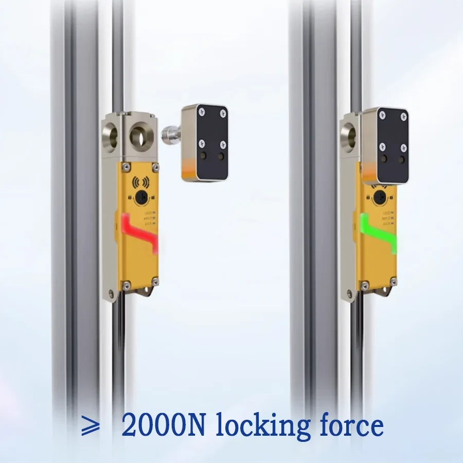
DX-D6 guard-locking switch installed on an access-door frame
Match the bracket to the actuator and the door
The DX-D6 actuator and bracket options list the DX-K9 coded actuator family and separate bracket options for hinged and sliding doors. Check the actual handing against the accessory drawing. The supplier can then identify the matching bracket and actuator for the selected switch. A similarly shaped key from another family is insufficient evidence of compatibility.
The mechanical selection section of the door switch guide explains why actuator choice follows the door motion and the exact switch family. Obtain the current mounting drawing and instructions for the selected hardware. Leave a service path to the fasteners and cable, and check cable movement at both ends of the door travel. A strain relief that looks clear with the door shut may be pulled into a pinch point when it opens.
Use the first inspection as the maintenance baseline
Record the bracket and actuator references with the approved door drawing. Document how the door sits at the stop and which points show whether it has moved. During a controlled inspection after a hinge repair, compare the door against that reference before treating an intermittent indication as an electrical fault. Moving the switch until its indicator comes on can conceal a problem with the frame, stop or hinge.
Any mechanical change must be reviewed against the applicable installation instructions and the validated safety function. A technician can use the door drawing to identify what has moved, while qualified commissioning personnel verify the required closed and locked states and the machine response. A latch that engages is one observation in that acceptance, with the complete safety function still to be verified.
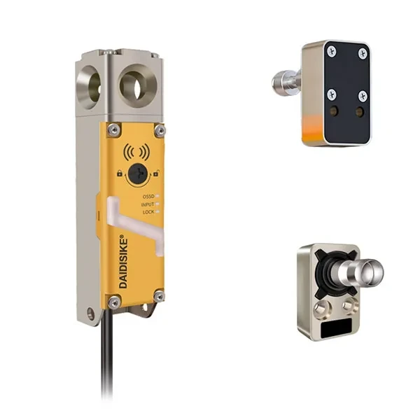
DX-D6 switch with coded actuator and connection hardware
